Structural Framework Update — Project Helix
Structural Framework
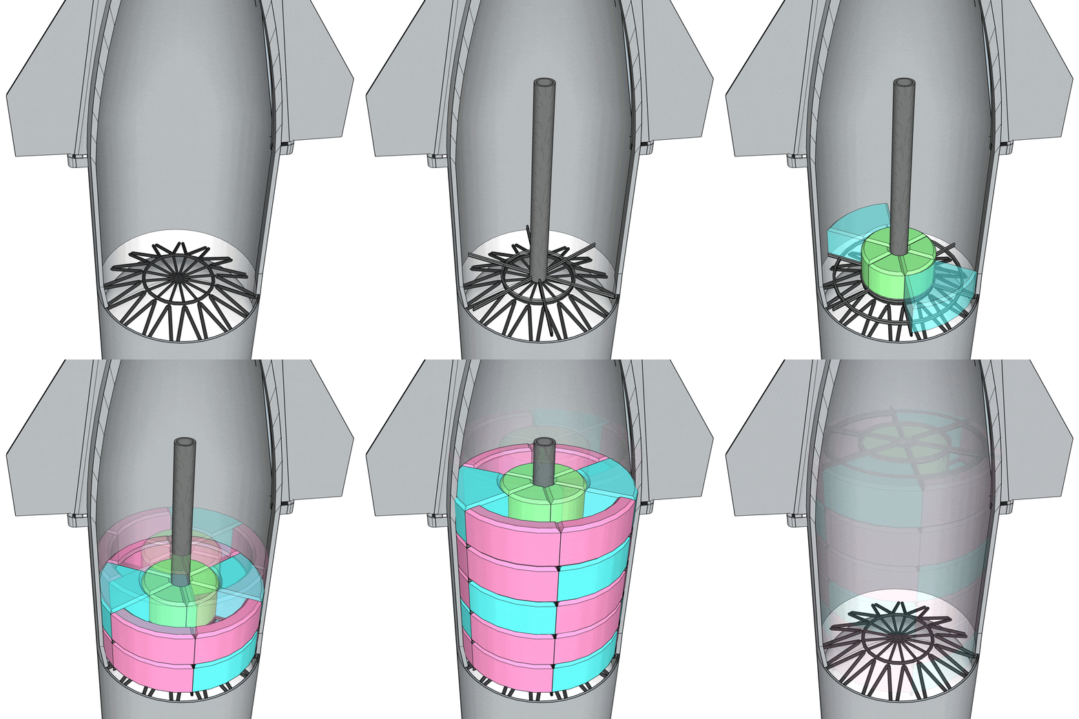
The titular helical corridors of Project Helix are formed by the modular, segment-shaped enclosures that partition the pressurized volume of Starship. These modular enclosures are not intended to be load-bearing, but rather attached to a support framework; a network of load-bearing beams. The layout of this framework should compliment the form of the modules themselves and it is for this reason that the framework is radial, connecting the perimeter wall to a rigid core. Each level of the pressurized volume is supported by these beams, and each beam transfers any experienced load to the perimeter wall and the rigid core.
Structural Loads
Types of Loads
Static Loads: weight of the members under gravity
Dynamic Loads: forces on the body during both initial launch and orbital maneuvers
Thermal Loads: differential expansion due to uneven heating during launch, re-entry, or solar orientation, or differences in various material's thermal expansion
Pressure Loads: variation in pressure difference between interior/exterior, for example: pre-launch vs coasting vs post-landing
Load Scenarios
Launch
Increased static load (acceleration)
High dynamic loads (vibration)
Thermal loads (change in thermal expansion due to tank depletion and atmospheric friction)
Re-entry
Increased non-axial static load (acceleration)
High dynamic loads (vibration)
High thermal loads (heating due to pressure-induced plasma formation)
Docking
Dynamic loads (sudden changes in acceleration and localized torques)
Normal Operations
Pre-launch
Static load (acceleration due to gravity)
Thermal load (change in thermal expansion due to tank filling)
Coasting
No significant static or dynamic (null-gravity)
Thermal loads ( uneven heating due to solar orientation)
Post-landing
Static load (acceleration due to gravity)
Thermal load (change in thermal expansion due to gradual cooling)
Emergency Conditions
Air leak or thruster malfunction
Static/Dynamic load (centrifugal and/or non-axial acceleration)
Pressure load (potential rapid change in pressure differential)
Collision
Dynamic, potentially non-axial, load (due to sudden change in acceleration and/or structural deformation under load)
Could lead to other conditions such as leaks or decompression
Design Responses
Radial beams increase resilience under non-axial acceleration.
Radial beams efficiently transfer loads to the perimeter wall and rigid core.
Lateral thermal expansion and differential pressure can be accommodated through the use of slots rather than holes in the beam connections to the perimeter wall and the rigid core. Other methods of non-plastic, transient load absorption may be used as well.
Beam Profile
The radial beam profile design is informed by the following consideration areas: reduction of intrusion, beam performance, and service integration.
Reduction of Intrusion into Modules
Allocating an entire structural layer for each "floor" of the spacecraft interior is wasteful at this scale. Instead, the modules should be "joined up" to each other and the beams should support these modules from the corners, increasing the functional volume of Starship.
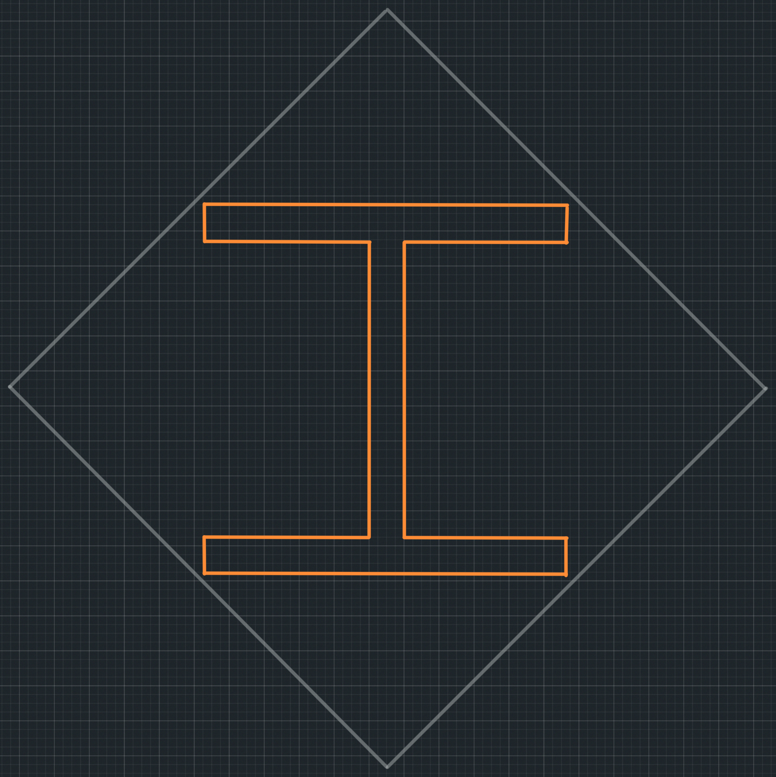
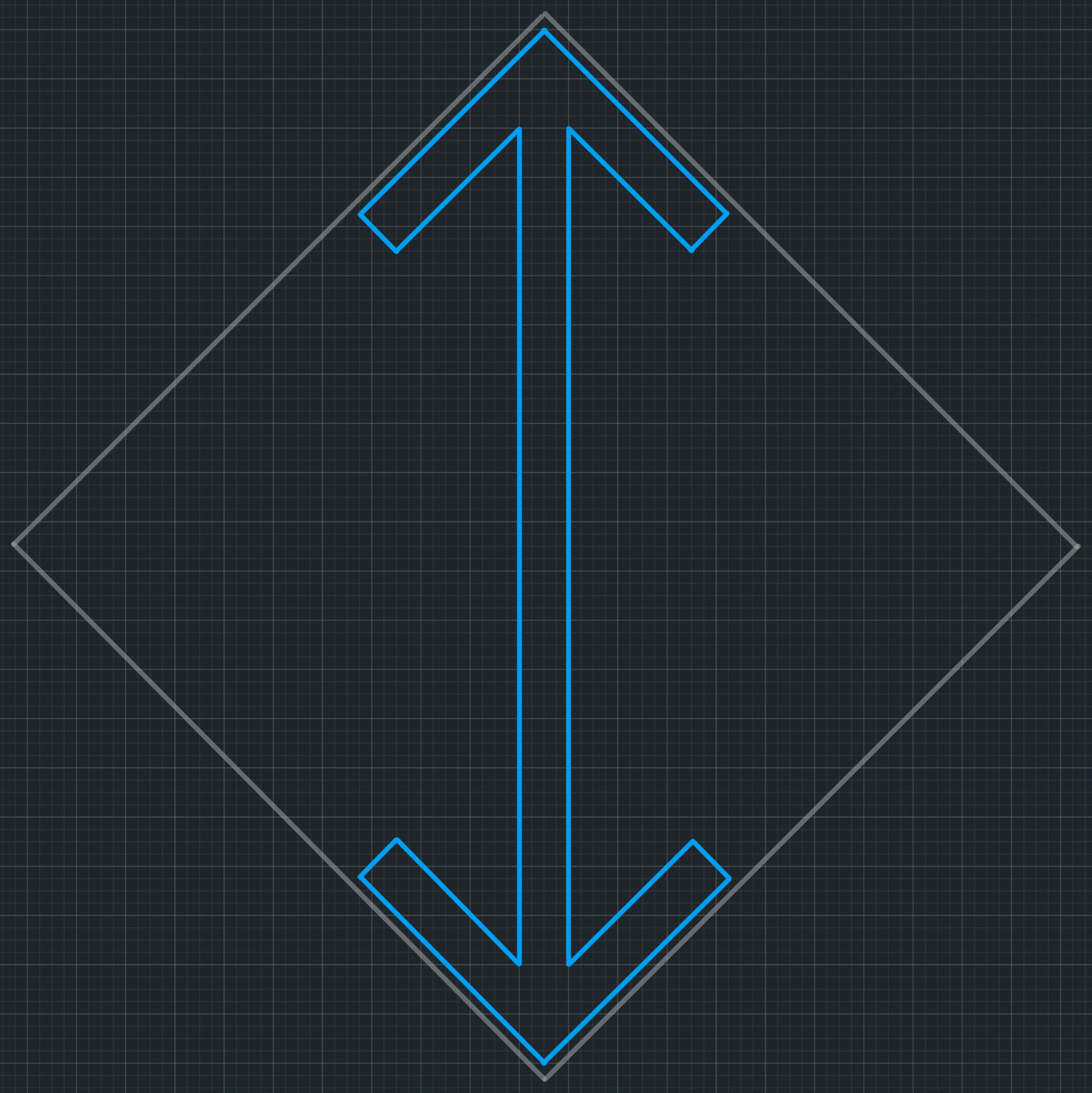
In order to reduce the intrusion of the beam into the modules, the beam should not create any convex block-outs in the module perimeter. This implies that the block-out for a beam must be angled with respect to the planes of the walls/floors. In section, this would create a diamond shape for the beam to occupy.
Beam Performance
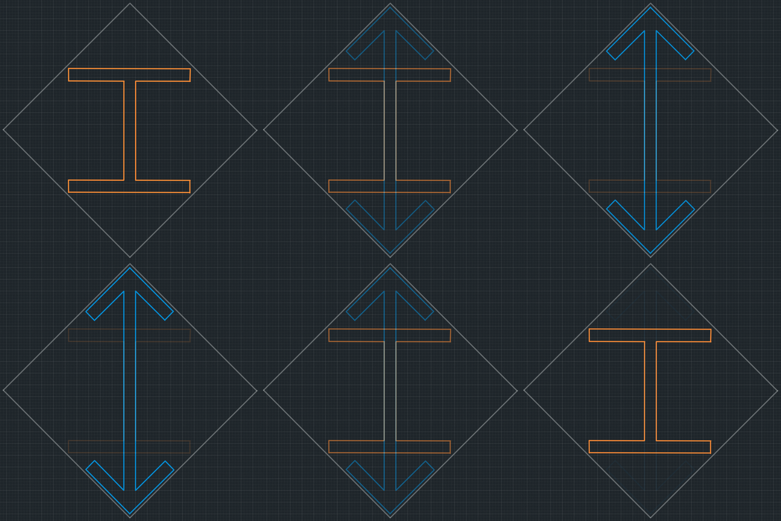
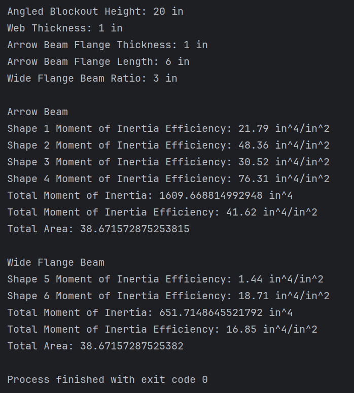
A conventional beam differs from the proposed profile in that a conventional beam typically supports a flat surface with respect to the neutral axis. This results in a profile extent that is largely rectangular. A rectangular beam extent cannot economically fit within the angled block-out mentioned in the previous section. Since much of the beam's performance is determined by the distance between the beam material and the neutral axis, allowing the profile of the beam to hug the top of the angled block-out has a positive impact of the efficiency of the beam. An efficient beam profile is one that locates material as far from the neutral axis as practical, as this reduces the bending stress experienced by the beam. As it happens, this is the same reasoning that gives rise to the wide-flange ("W") profile. In the case of an angled block-out, such a profile would resemble a wide-flange profile, however the top and bottom flanges would be angled like arrows. For this reason, I would like to coin the term arrow flange to describe this beam construction.
While there are several equations that are used to assess the strength of a beam profile, they all display that the moment of inertia is arguably the most important and ubiquitous property. In all cases, since the moment of inertia is in the denominator position, a reduction is seen in the structural stress and displacement as the moment of inertia increases. All things being equal, a higher moment of inertia yields a stronger beam.
By conducting moment of inertia calculations for wide flange and arrow flange beams fitting in an angled block-out, it has been confirmed that the performance of an arrow flange beam is more than twice that of a wide flange beam using the same amount of material. The superior performance of the arrow flange beam can even go up to 4.5 times that of the wide flange beam, depending on the wide flange beam's height-to-width ratio. A ratio of 1:1 (ie: a beam that is as high as it is wide, as in the illustration) yields a moment of inertia 4.5 times lower than that of an arrow beam using the same amount of material.

Service Integration
Any wide flange beam contains empty space between the outer edges of its flanges. In typical buildings, the cavity between ceiling and floor (the minimum dimension of which is defined by the height of the beam) is used for air/plumbing/electrical services, but is otherwise non-habitable volume. This is completely typical and expected in terrestrial construction, however the employment of this paradigm is by no means necessary for space design. Instead of dedicating an entire layer to structure and services, these necessities could occupy a much smaller footprint.
The space between the beam flanges can be used to run services from the core to each individual module. As such, there should be enough open space around the neutral axis of the beam to 'daylight' these services to the module interior.


